
Wind Turbine Drivetrain Test Bench Design, a Reflection
Published:
My Experience
I have had the unique opportunity to work on parts of the systems located at the wind turbine test bench in North Charleston, SC. The test bench as shown in figure 1, is capable of testing various different kinds of load cases on the input shaft of the turbine housed within the nacelle. I cannot share any details of the work that I did because I signed a non-disclosure agreement. Having some background experience with this system will provide a different perspective as to how I interpret and understand the content of this report. A good friend of mine works at this facility as a test bench operator and I wondered about how the control systems for applying the loads on the turbine responded during real tests.
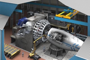
Figure 1. Rendering of the wind turbine test bench in North Charleston, SC. [3]
Purpose and Expectations
Before reading the report [1] [2] I considered several things. I was curious to find out how the reaction forces and stresses on the turbine members would be analyzed and what the designers of these systems would want to know in order to improve the efficiency of the wind turbine design. The shear power of a 15MW wind turbine is outstanding, and how you begin to consider the magnitude of stresses enacted on the internal components and supporting structures is extraordinary to imagine. I looked forward to seeing the results from the case study and build upon my initial assumptions of what I imagined the system would be like. The purpose of this report is to provide a methodology for test benches that are configured like the one shown above. I can understand why building and performing these load tests are cost effective and necessary for wind turbine development. Designers of these several hundred-ton components need to better understand the forces acting on their components under a variety of combined loading conditions in order to reduce the weight of the rotating components in the system. If the weight can be reduced, then the efficiency of the system is increased, and more power can be generated. Right now, wind power does not carry with it the energy density it needs to replace fossil fuel driven power solutions. The experiments done on these kinds of test benches will provide the data to drive the next generation of wind turbines that will tilt the scales in favor of renewable energy.
Reflections
The load application unit (LAU) is coupled with a motor that provides the torque to the input shaft of the turbine itself. The ramp rate in which loads can be applied must be carefully controlled and is limited to the motors ability to produce the requested torque ramp, as well as the LAU’s ability to shift loading. These two limiting factors of the test bench have to be considered when developing a run program for the test bench. I thought that it was interesting that load cases were considered in which the turbine blade was damaged. This is obviously important to investigate, and something that really grabbed my attention. Quantification of the ability to perform a ramp via the motor or LAU using a capability ratio is a great way to convey the limitations of what the bench is capable of simulating. The paper states it well, saying that the test engineer or operator can determine if a specified ramp rate is possible by referring to the capability ratio as a statistical approach to the system limitations. Bearing in mind that this paper was written with the intent of providing guidance to others who might be interested in developing such a test bench, this concept is extremely valuable from a design prospective. The case study provides context to the first paper by exploring the system capability of the test bench referred to earlier in figure 1. Using data to provide a practical example of how to better interpret the capability space of the test stand is a powerful tool that those interested in pursuing the design of their own test bench can grasp.
Next Steps Moving Forward
Further insight into how load cases beyond the capability region should be assessed on a case by case basis depending on the controller used at the test bench. The paper offers a generalized guide for the operating space within the design criteria of the stand, but if a extraordinarily high ramp rate is needed there is no guidance provided on how the impact of adjusting the controller to reach these desired rates should be approached.
Conclusion
This paper describes well the general guidelines and methods that should be considered when creating a run program for a wind turbine test bench. I thought that the paper did a great job generalizing the approach to a standard set of guidelines that should be considered by the test engineer when designing run programs. This paper is groundbreaking in that it provides the context for a test stand versus all other literature that only focuses on prototype testing. It was interesting to read about the LAU and how it added to the complexity of the controls of the system. The two part paper uses practical data to provide context to a novel system in a straightforward and easy to visualize manner. I learned more about how the bench operates and what kind of combined loading cases are reasonable to see on a test bench like this.
References
[1] Giguère, P, & Wagner, JR. “Wind Turbine Drivetrain Test Bench Capability to Replicate Design Loads: Part I — Evaluation Methodology.” Proceedings of the ASME 2017 11th International Conference on Energy Sustainability collocated with the ASME 2017 Power Conference Joint With ICOPE-17, the ASME 2017 15th International Conference on Fuel Cell Science, Engineering and Technology, and the ASME 2017 Nuclear Forum. ASME 2017 11th International Conference on Energy Sustainability. Charlotte, North Carolina, USA. June 26–30, 2017. V001T13A004. ASME. https://doi.org/10.1115/ES2017-3595.
[2] Giguère, P, & Wagner, JR. “Wind Turbine Drivetrain Test Bench Capability to Replicate Design Loads: Part II — Case Study of a Multi-MW Drivetrain.” Proceedings of the ASME 2017 11th International Conference on Energy Sustainability collocated with the ASME 2017 Power Conference Joint With ICOPE-17, the ASME 2017 15th International Conference on Fuel Cell Science, Engineering and Technology, and the ASME 2017 Nuclear Forum. ASME 2017 11th International Conference on Energy Sustainability. Charlotte, North Carolina, USA. June 26–30, 2017. V001T13A005. ASME. https://doi.org/10.1115/ES2017-3611.
[3] “Clemson University Wind Turbine Drivetrain Test Facility.” Engineers, Project Managers & Consultants, Charleston, SC, Live Oak Consultants, 16 Feb. 2017, liveoakconsultants.com/educational/clemson-wind-turbine/.